JOINTS IN THE STRUCTURES
Figure given is the typical frame structure. We solved such types of structures in "Strength of material" in Undergraduates. The major parameters require to be structural members are material property, sectional properties, boundary conditions also known as supports and loads.
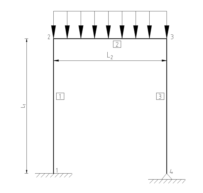
Material property is governed by Modulus of Elasticity (\(E_s\)), where as sectional properties are governed by Area (\(A\)) and Moment of Inertia (\(I\)). Axial members such as trusses, columns, struts etc need Area, whereas flexural members such as beams need Moment of Inertia as the sectional properties. Loads are calculated and assigned according to the procedures mentioned in the codes or general practices. But, selection of the supports in concrete structures is very complex.
Fixed supports in concrete section are comparatively easier to provide practially than hinge supoort. By extending adequate amount of reinforcement with development length might fulfill the requirement for fixed support but it is very difficult to make hinge support. Then how to make hinge support at the bottom. Lets have some discussion
We all know following properties of joints
| SN | Joint name | Symbol | Forces | Deflection/rotation | ||||||||||
| \(F_x\) | \(F_y\) | \(F_z\) | \(M_x\) | \(M_y\) | \(M_z\) | \(\delta_x\) | \(\delta_y\) | \(\delta_z\) | \(\theta_x\) | \(\theta_y\) | \(\theta_z\) | |||
| 1. | Fixed |
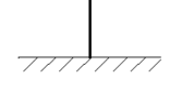
|
1 | 1 | 1 | 1 | 1 | 1 | 0 | 0 | 0 | 0 | 0 | 0 |
| 2. | Hinged |
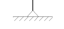
|
1 | 1 | 1 | 0 | 0 | 0 | 0 | 0 | 0 | 1 | 1 | 1 |
| 3. | Roller |
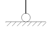
|
0 | 1 | 1 | 0 | 0 | 0 | 1 | 0 | 0 | 1 | 1 | 1 |
The joint in structure should follow the above criteria. The loads tranfer mechanism in the joint should also satisfy.
1. SUPPORT (JOINT) AT THE BASE OF COLUMN.
In this case the support should transfer moments, shear forces and axial forces. Most of the Structural Engineers do only design structural members such as compression members (columns) and foundation (Either isolated, raft or pile), but not the joint between these structural members.
Different codes give the load tranfer mechanism. As per IS 456:2000 (Clause 34.4),
the compressive stress in concrete at the base of a column or pedestal shall be considered as being transferred by bearing to the top of pedestal or footing.
The bearing pressure on the loaded area shall not be exceeded the permissible bearing stress in direct compression multiplied by a value equal to
Where,
\(A_1\) = supporting area for bearing of footing, which in sloped or stepped footing may be taken as the area of the lower base of the largest frustum of a pyramid or cone contained wholly within the footing and having for its upperbase, the area actually loaded and having side slope of one vertical to two horizontal; and
\(A_2\) = loaded area at the column base.
\(A_1\) and \(A_2\) are illustrated in the figure below.
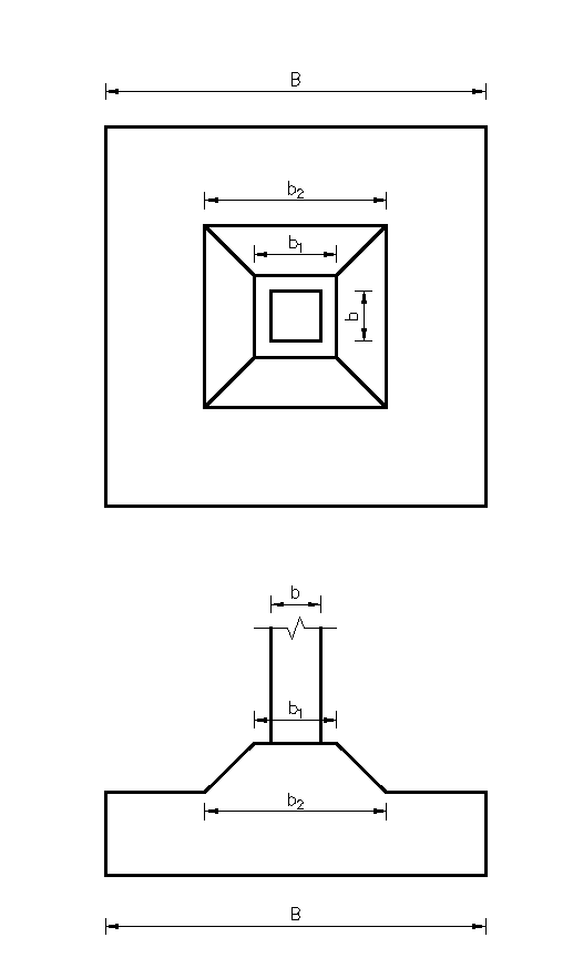
Assuming square column and footing
Area \(A_1 = b_2^2\)
\(A_2= b^2\)
Permissible bearing stress is given by,
And actual bearing stresses shall be calculated by principle of bending,.
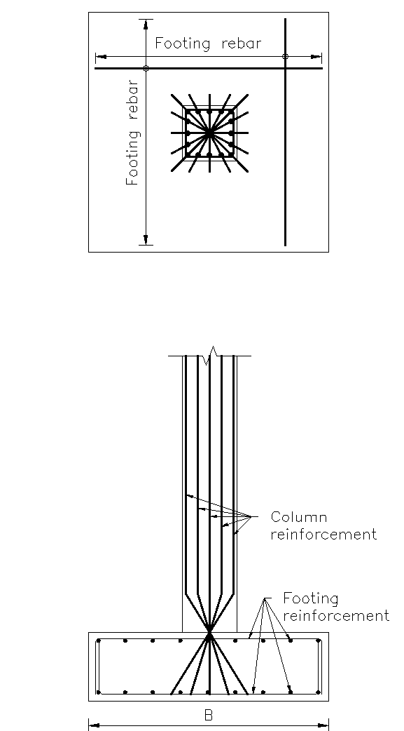
If \(\sigma_{(x,y)} > \sigma_b\), then the reinforcement should transfer the forces (axial, moments and even shear) to the foundation. In practice, we extend all the reinforcement coming from column to the foundation. Such types of connections are the fixed connection. Then, how can we make hinge/pinned connection?
We know that hinge connection have many advantages. In structural analysis point of view, it is easier to analyze. The section may be smaller in size and may require less reinforcement. The requirement of large section and reinforcement in columns are generally due to uniaxial or biaxial moments. So, again question is how to make the support hinge in concrete section.
In flexural member, moment of resistance is given by
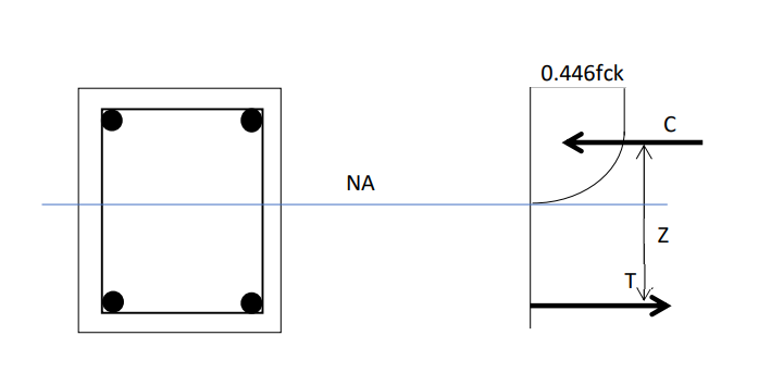
In the above equations, if we consider \(z=0\) then moment of resitance \(M_R=0\) then this section does not carry any moment in that direction. Therefore, the section can transfer only tension (or compression) if \(z = 0\) in both direction. This condition is illustratred by following figure. Still it may carry a small amount of moment.
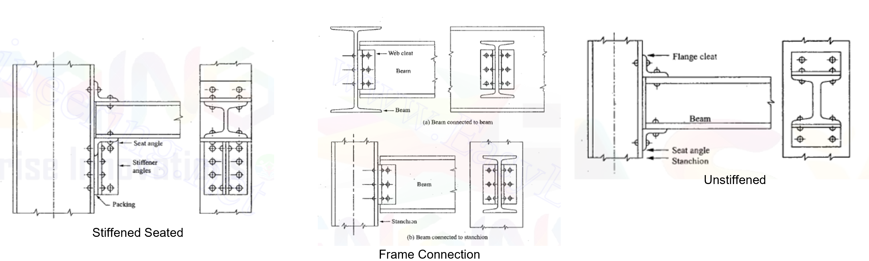
In case of Steel Connection, the hinge connections are easily installed as given in the figure below.
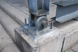
However, still the connection between steel and concrete should be designed for pure compression & shear due to horizontal component of load coming from column.
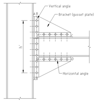
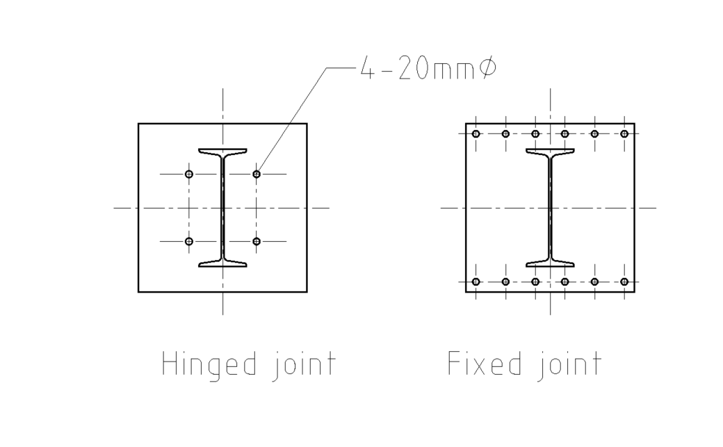
In case of moment connection at the bottom of column, we have to make some arragement of bolts around the column so that the connection can be made fixed. For fixed (moment) connection, the bolts should carry moments \(M_i=P_iz_i\) which is developed by the moment arm (\(z_i\)) between the center of section and the bolts and the tension at the bolts (\(P_i\)) . Therefore, the moments connection should have large \(z\). Mathematically in case of \(\sigma_{(x,y)} < \sigma_b\), some anchors will have tensions (\(P_i\)) and they should have large \(z_i\). The two types joint are differentiated by following figure.
2. JOINTS IN TRUSS MEMBERS
What is the difference between bolted conncection or welded connections in truss? It is not always necessary to become the members connected by bolts is pinned. However, they can be made pinned by providing suitable arrangement. The members connected by weld may carry moments and such connection can't be treated as the pinned connection.
But due to the nature of truss, even welded joints have very little or almost zero moments.
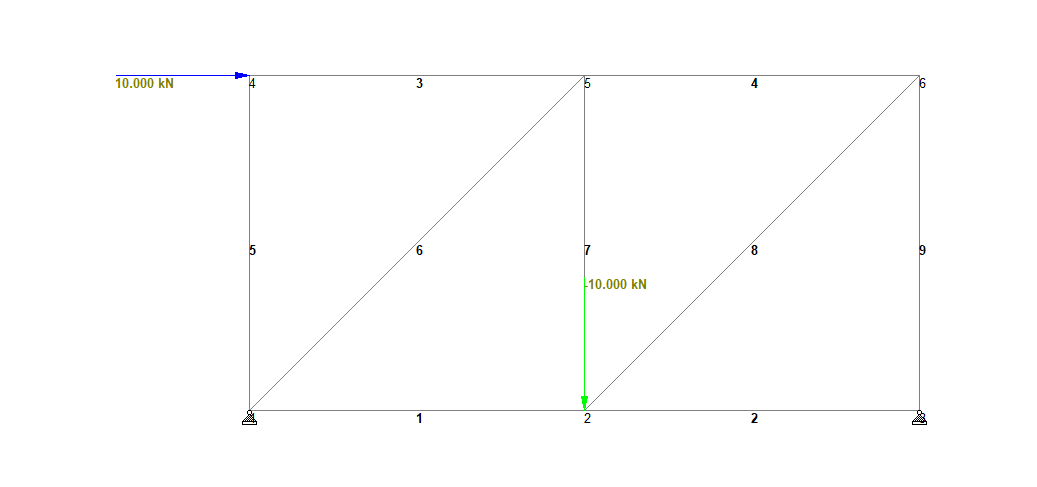
According to the table above, the moments are significantly small and can be neglected in the joint design and therefore welded joint can be designed in the truss
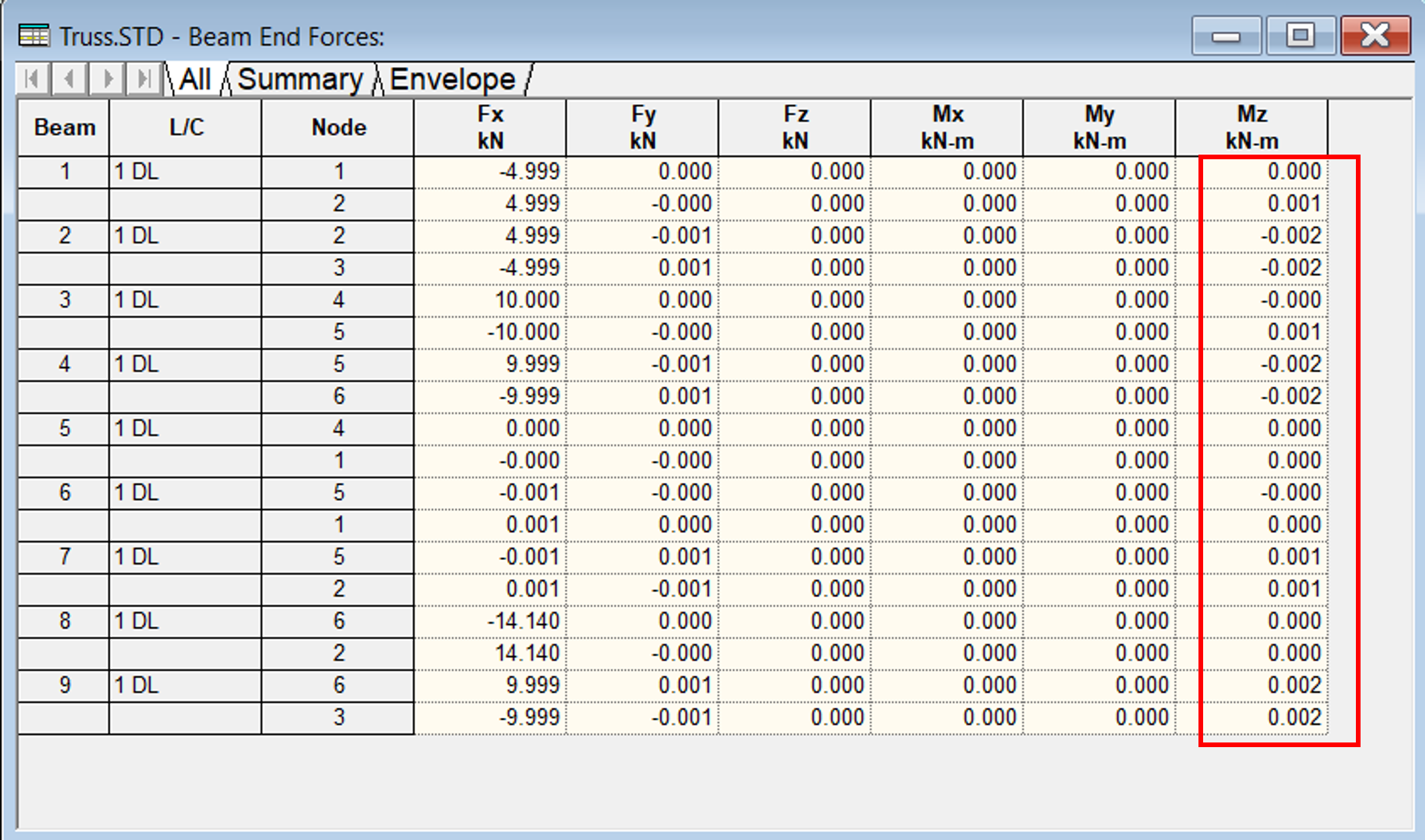
We also tested the truss by providing joints with the release of moments as given below.
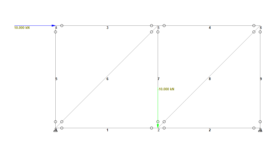
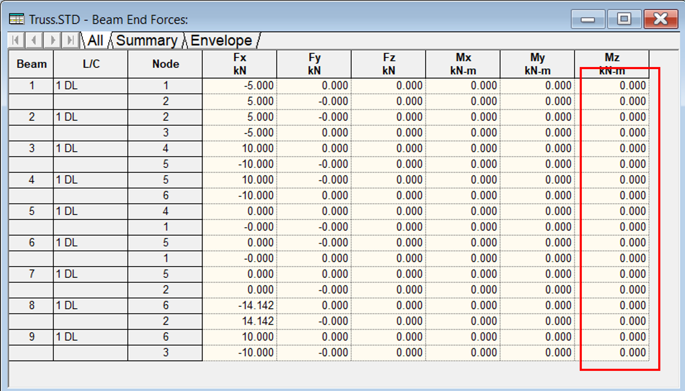
From the above two examples, we knew that the joints in truss can be designed as both bolt or welded connections.
3. COLUMN-BEAM JOINTS
In concrete structure, moment connection have been provided in most cases by providing adequate reinforcement with development length.
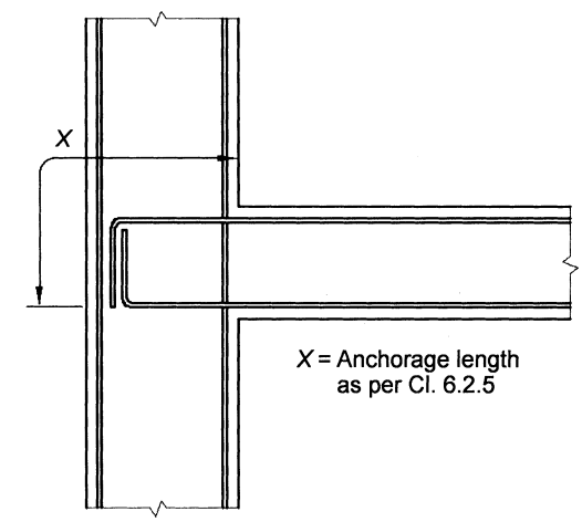
IS 13920 - 2016: Ductile detailing of Reinforced Concrete Structures Subjected to Seismic Forces-Code of Practice , gives the detail for the requirement of the moment connection between beam and column. As per Clause 6.2.5, At an external joint, top and bottom bars of beams shall be provided with the anchorage length (\(X\)) beyond the inner face of the column, equal to development length of the bar in tension plus 10 times bar diameter minus the allowance for \(90^o\) bends
The requirement of design strength of column and beam as per Clause 7.2.1 is given by following figures.
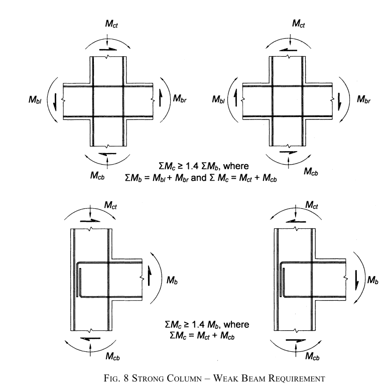
The design moments of the resistance of a beam shall be estimated based on the principles of mechanics and the limiting strain states of the limit state design method enunciated in IS 456.The design moment of resistance of a column shall be estimated as in case of beams corresponding to zero axial forces on the design \(P-M\) interaction diagram.
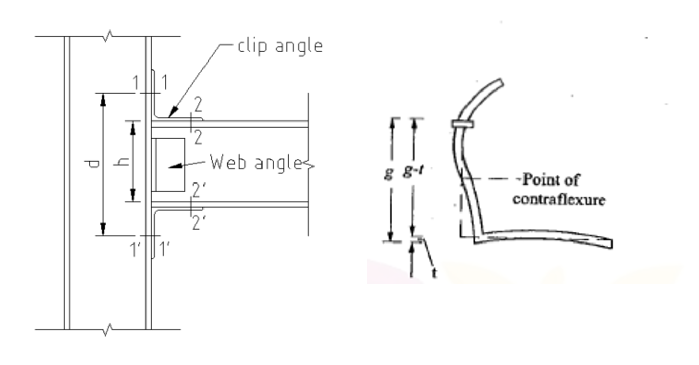
In case of steel structures, the joint can be made for shear, small moments and large moments by arranging and providing bolts, cleats, sheets above and below the beam as given in the figure below.