PRESSURE OF FRESH CONCRETE ON VERTICAL FORMWORK
The fresh concrete pressure shall be calculated according to DIN 18218:2010-1 Pressure of fresh concrete on vertical formwork. According to the code, the pressure shall be calculated according to (Cl. 4.2) and Table 1 and 2.
The design of formwork and falsework including anchoring shall be based on the design value of the fresh concrete of
Where
\(\sigma_{hd}\) = Design concrete pressure
\(\sigma_{hk}\) = characteristic value of concrete pressure
\(\sigma_F\) = Partial safety factors
The partial factors shall be adopted as given below.
1. For unfavourable actions
1. For favourable actions
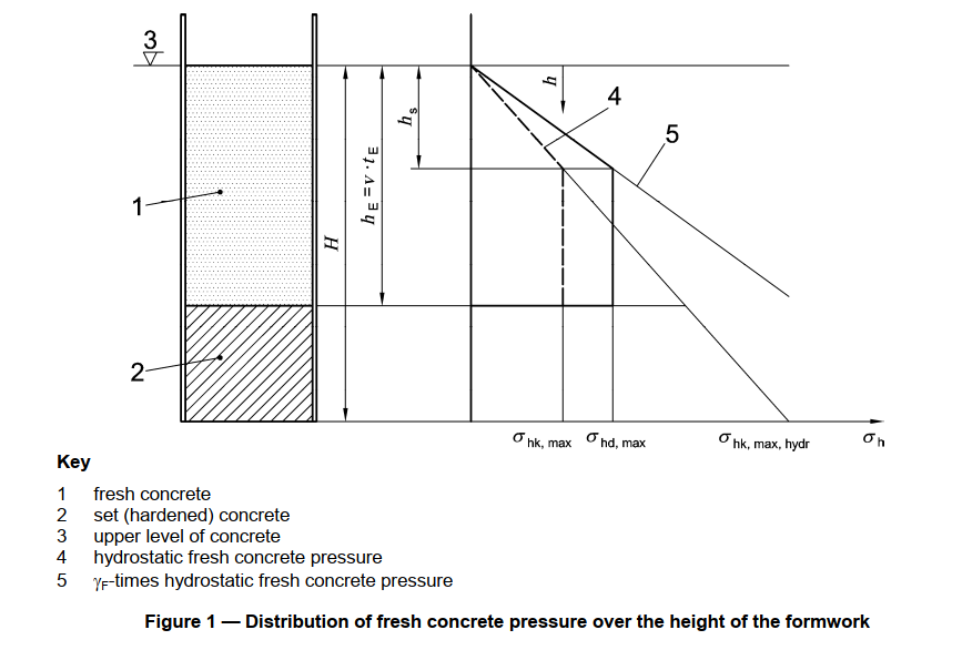
The figure below demonstrated the distribution of fresh concrete pressure.
The concrete pressure is given by the following relations
| 1 | 2 | |
| 1 | Consistency class | Maximum lateral fresh concrete pressure when placed in opposite direction to the the rise in level (from above) \(\sigma_{hk,max}\) kN/m2 |
| 2 | \(F_1\) | (\(5.ν+21).K1 \geq 25\) |
| 3 | \(F_2\) | (\(10.ν+19).K1 \geq 25\) |
| 4 | \(F_3\) | (\(14.ν+18).K1 \geq 25\) |
| 5 | \(F_4\) | (\(17.ν+17).K1 \geq 25\) |
| 6 | \(F_5\) | (\(25+30.ν).K1 \geq 30\) |
| 7 | \(F_6\) | (\(25+38.ν).K1 \geq 30\) |
| 8 | \(SCC\) | (\(25+33.ν).K1 \geq 30\) |
Where \(\nu \) is the placing rate(pouring rate) in m/h
\(K1\) is the factor taking into account the setting behaviour according to Table 2.
| 1 | 2 | 3 | 4 | 5 | |
| 1 | Consistency class | ||||
| 2 | End of setting \(t_E =5 \) h | End of setting \(t_E =10 \) h | End of setting \(t_E = 20\) h | Generalb | |
| 3 | \(F_1^a\) | \(1.0\) | \(1.15\) | \(1.45\) | \(1+0.03(t_E-5)\) |
| 4 | \(F_2^a\) | \(1.0\) | \(1.25\) | \(1.80\) | \(1+0.053(t_E-5)\) |
| 5 | \(F_3^a\) | \(1.0\) | \(1.40\) | \(2.15\) | \(1+0.077(t_E-5)\) |
| 6 | \(F_4^a\) | \(1.0\) | \(1.70\) | \(3.10\) | \(1+0.14(t_E-5)\) |
| 7 | \(F_5, F_6, SCC\) | \(1.0\) | \(2.00\) | \(4.00\) | \(\frac{t_E}{5}\) |
a Applies for concreting section of a height \(H\) up to 10m.
b Applies for 5 h \(\leq\) h; \(t_E\) in h.
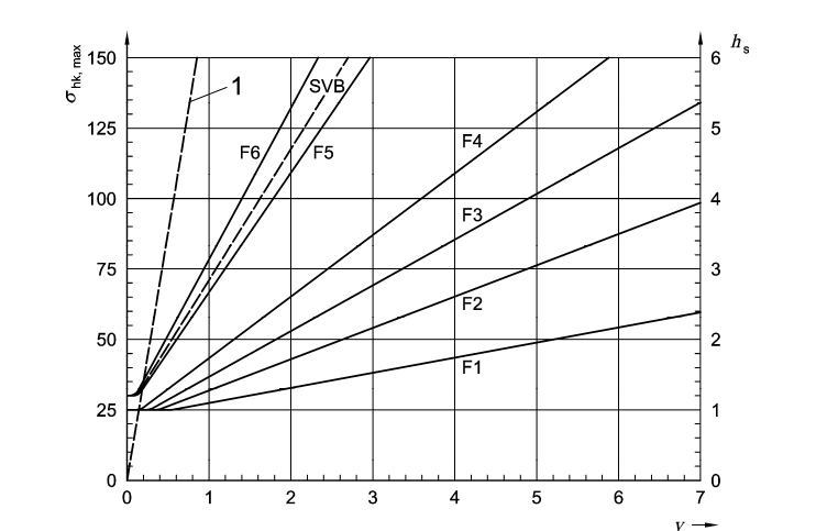
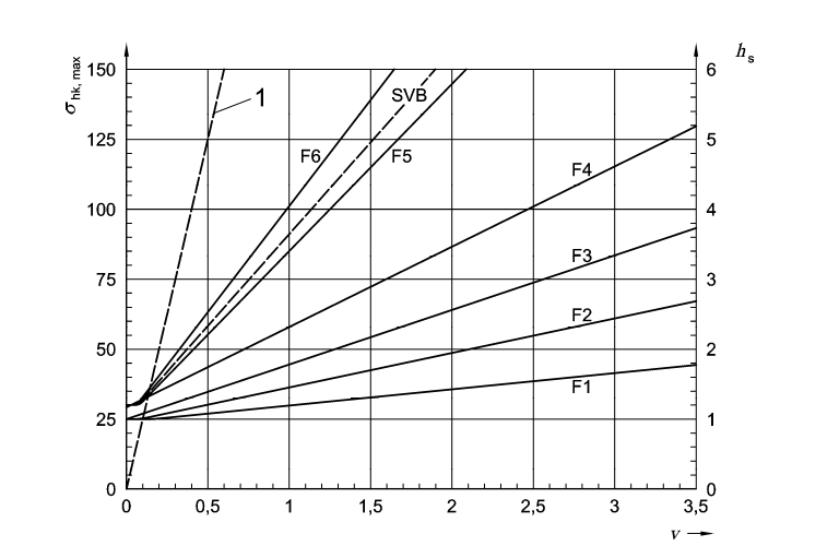
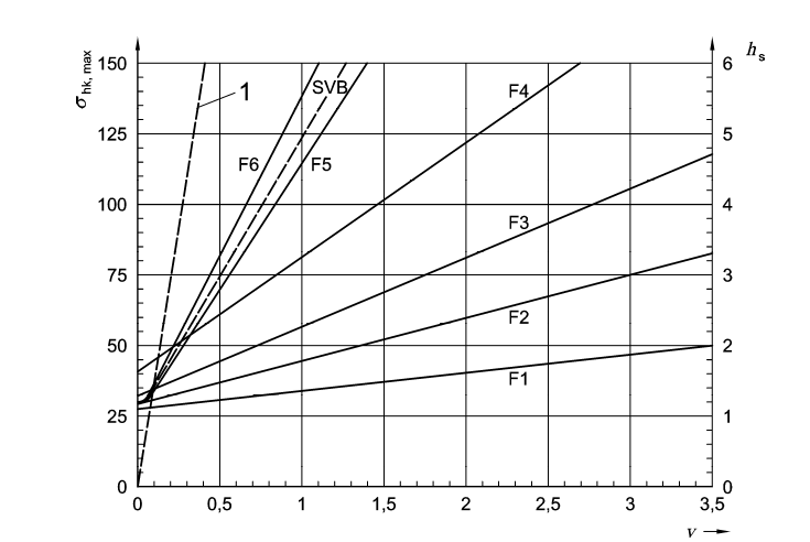
The same can be derived from the figures below
1. When, \(t_E=5h\)
2. When, \(t_E=7h\)
3. When, \(t_E=10h\)
4. When, \(t_E=15h\)
5. When, \(t_E=20h\)
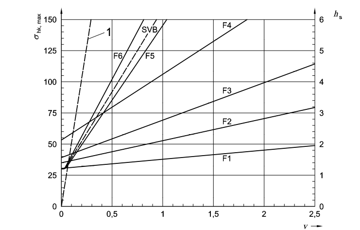
In above figures, the density of fresh concrete has been taken as \(\gamma_c=25 kN/m^3\)
Consistency class has been catagorized as \(F_1, F_2, F_3, F_5\), \(F_6\) and SCC can shall be found by lab tests. Flow table test according to DIN EN 1235-5 is used.
Symbols
\(h\)= height of concrete
\(h_E\)= height of concrete at the end of setting \(t_E\)
\(h_s\)= hydrostatic pressure head
\(h_v\) = depth of penetration of internal vibrator
\(H\)= overall height of building to be poured
\(t\)= time
\(t_E\)= end of setting time
\(T\)= temperature
\(v\)= placing rate
\(\gamma\)= density or partial safety factors
\(\gamma_c\)= density of concrete
\(\sigma\)= stress
\(\sigma_{h}\)= lateral fresh concrete pressure
\(\sigma_{hd}\)= design value of lateral fresh concrete pressure
\(\sigma_{hk}\)= characteristics value of lateral fresh concrete pressure
According to the pressure distribution, the force at each position of beams, columns, anchors and plates (steel or wood) calculated and designed accordingly.
Additionally, the concrete pressure can be calculated by CIRIA Report -8 1985The concrete pressure on formwork is calculated based on CIRIA (Construction Industry Research and Information Association, Report -8 1985
The concrete pressure in \(kN/m^2\) on formwork is given by;
Where,
\(C_1\) = coefficient dependent on the size and shapes of formwork (Table for values),\(\sqrt(mh)\)
\(C_2\) = coefficient dependent on the constituent materials of the concrete (see Table for values), \(\sqrt(m)\)
\(D\) = weight density of concrete, \(kN/m^3\)
\(H\)= vertical form height, m
\(h\) = vertical pour height, m
\(K\) = temperature coefficient taken as \((\frac{36}{T+16})^2\)
\(R\) = the rate at which the concrete rises vertically up the form, m/h
\(T\) = concrete temperature at placing \(°C\)
When \(C_1\sqrt(R) >H\), the fluid pressure (\(Dh\) should be taken as the design pressure.
The term \(C_1\sqrt(R)\) incorporates the effect of vibration and workability, because these factors are largly dependent on size, shape and rate of rise. All the effects of the height of discharge, cement type, admixtures, and concrete temperature at placing are incorporated in the term:
Table: Values of coefficients \(C_1\) and \(C_2\)
| Wall: | \(C_1\) = 1.0 |
| Columns: | \(C_1\) = 1.5 |
| Concrete | values of \(C_2\) |
| OPC, RHPC of SRPC without admixtures | \(0.3\) |
| OPC, RHPC of SRPC with any admixture, except a retarder* | \(0.3\) |
| OPC, RHPC of SRPC with a retarder | \(0.45\) |
| LHPBFC, PBFC, PPFAC or blends containing less than 70% ggbfs or 40% pfa without admixtures | \(0.45\) |
| LHPBFC, PBFC, PPFAC or blends containing less than 70% ggbfs or 40% pfa with any admixtures, except a retarder* | \(0.45\) |
| LHPBFC, PBFC, PPFAC or blends containing less than 70% ggbfs or 40% pfa with a retarder** | \(0.6\) |
| blends containing less than 70% ggbfs or 40% pfa with a retarder** | \(0.6\) |
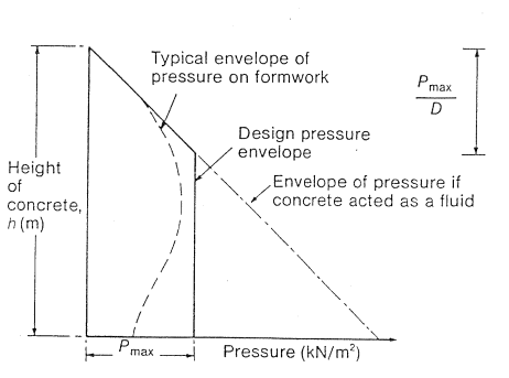
Figure below shows the envelope comprises fluid pressure to the depth where maximum pressure obtained from the design equation or chart occurs and then remains at this value