DESIGN OF CONCRETE SECTION AS PER IS 456:2000
MATERIAL SAFETY FACTORS
The material safety factors have been assumed for concrete and steel as given below
For Concrete \( \gamma_m = 1.5 \)
For Steel \( \gamma_m = 1.15 \)
STRESS-STRAIN CURVE OF CONCRETE
The parabolic Stress-strain curve is given as follow. The relationship with stress and strain is also provided below.

If Strain \(ε<0.002\) the stress\(f_c\) is given by:
Otherwise, If
stress is given by,
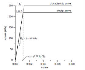
STRESS-STRAIN CURVE OF STEEL
Stress-strain curve is linear in mild steel (Fe250). The relation is shown as given below.
| Stress | Inelastic strain |
|---|---|
| 0.80fy | Nil |
| 0.85fy | 0.0001 |
| 0.90fy | 0.0003 |
| 0.95fy | 0.0007 |
| 0.975fy | 0.0010 |
| 1.0fy | 0.0020 |
Similarly for Tor Steel, Stress-strain curve is given as follows. The numerical value of this relation has been provided in table below. The intermediate values can be calculation using linear interpolation.
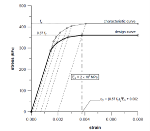
| Stress | Inelastic strain |
|---|---|
| 0.80fy | 0.00144 |
| 0.85fy | 0.00163 |
| 0.90fy | 0.00192 |
| 0.95fy | 0.00241 |
| 0.975fy | 0.00276 |
| 1.0fy | 0.00380 |
| Stress | Inelastic strain |
|---|---|
| 0.80fy | 0.00174 |
| 0.85fy | 0.00195 |
| 0.90fy | 0.00226 |
| 0.95fy | 0.00277 |
| 0.975fy | 0.00312 |
| 1.0fy | 0.00417 |
STRESS AND STRAIN DIAGRAM OF THE SECTION
The relation is given as follows.


Total compressive force,
And centroid of the compression block,
And
\( x_{u,lim} = kd \)Where,
Moment of resistant for singly reinforced section;
The singly and doubly reinforced section shall be differentiated by calculated by moment of resistance as given above. If \(M_u>M\),Singly reinforced otherwise Doubly reinforced section.
The moment of resistance can be calculated by;
For singly reinforced section:
Area of reinforcement for singly reinforced section can be calculated by;
The design of doubly reinforced section can be calculated by the following relations
Also,
\(f_{sc}\) can be calculated using strain diagram as given below.

Using the stress-strain diagram of steel, \(f_{sc}\) shall be calculated for strain, \(ε_{sc}\)
Or using the following table, \(f_{sc}\) can be calculated.
Stress in Compression reinforcement \(f_{sc}\) in doubly reinforced beams with cold-worked bars
| fy N/mm2 | d'/d = 0.05 | d'/d = 0.10 | d'/d = 0.15 | d'/d = 0.20 |
|---|---|---|---|---|
| 415 | 355 | 353 | 342 | 329 |
| 500 | 424 | 412 | 395 | 370 |
This table can be formulated as
i) For \(f_y = 250 N/mm^2\)
ii) For \(f_y = 415 N/mm^2\)
ii) For \(f_y = 500 N/mm^2\)
SHEAR REINFORCEMENT
Design shear strength of concrete is given by.
The value given in Table 19 of IS 456:2000 has been derived from this equation. the Correction factor for depth shall be incorporated in the above formula. The correction factor is given by Clause 40.2.1.
| Overall depth | ≥ 300 | 275 | 250 | 225 | 200 | 175 | ≤ 150 |
|---|---|---|---|---|---|---|---|
| K | 1.00 | 1.05 | 1.10 | 1.15 | 1.20 | 1.25 | 1.30 |
These values can be represented by following relations
If \(D \leq 150, K = 1.30 \)
If \(D > 300, K = -0.002D+1.6 \)
Where ,
Shear reinforcement requirement for vertical stirrups.
i) If \( \tau_v<\tau_c \), No requirement of shear reinforcement, however minimum shear reinforcement shall be provided as calculated by the following formula.
ii) If \(\tau_v>\tau_c \), shear reinforcement calculated as
In no case
The maximum shear strength \(\tau_{v,max}\) is given by Table 20 of IS 456:2000.
| Grade of concrete | M15 | M20 | M25 | M30 | M35 | M40 and above |
|---|---|---|---|---|---|---|
| \(τ_{c,max}\) | 2.5 | 2.8 | 3.1 | 3.5 | 3.7 | 4.0 |
Shear capacity of the section depends on concrete grade (\(f_{ck}\)), Area of tension reinforcement (\(A_{st}\)) and depth of section. The shear strength does not increase above M40 and the area of reinforcement increases strength slightly. Therefore, controlling factor for the shear capacity is depth of section.
MINIMUM AND MAXIMUM REINFORCEMENT
Flexural reinforcement shall not be less than
As Per IS 456:2000,
As per IS 13920: 2016 (6.2.1)
(26.5.2.1 Minimum reinforcement): The mild steel reinforcement in either direction shall not be less than \(0.15\)% of the total cross sectional area. However, this value can be reduced to \(0.12\)% when high strength deformed bar are used.
Maximum reinforcement in flexure \(= 0.04bD\)