STABLITY ANALYSIS OF GRAVITY DAM
Gravity dam shall be designed based on Indian Standards IS: 6512-1984
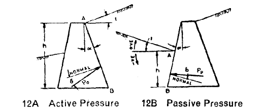
Active pressure coefficients for static condition
Passive pressure coefficients for static condition
In case of seismic condition, as per IS1893:1984 Clause 8.1.1, the active pressure coefficient shall be calculated as.
Where,
\(\alpha\) = Angle which the earth face of the wall makes with the vertical
\(i\) = Slope of earthfill
\(\delta\) = Angle of friction between the wall and earth fill
\(\alpha_h\) = Horizontal seismic coefficient
\(\alpha_v=\frac{2}{3}\alpha_h\) = vertical seismic coefficient
CALCULATION OF LOADS
1. DEAD LOAD (\(F_1\))
2. RESERVOIR AND TAILWATER LOADS (\(F_2\))
Reservoir pressure \(=F_{2R}\)
Tailwater pressure \(=F_{2T}\)
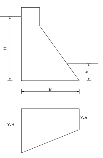
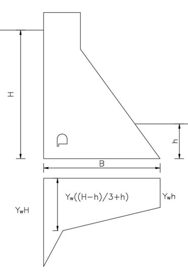
3. UPLIFT PRESSURE (\(F_3\))
Case A: Uplift pressure when drains are inappropriate, or no drain has been provided.
Case B: When drain are provided or approprite.
It is assumed that uplift pressures are not affected by earthquake.
|
|
| Case A: When drains are inappropriate, or no drains have been provided. \(F_3=\frac{B}{2}\gamma_w(H+h)\) |
Case B: When drain are provided or approprite.
\(F_{31}=\frac{b_1}{2}\gamma_w(H+h+\frac{H-h}{3})\) \(F_{32}=\frac{B-b_1}{2}\gamma_w(h+h+\frac{H-h}{3})\) |
4.EARTHQUAKE FORCES (\(F_4\))
Seismic load has been calculated based on IS 1893: 2002 or NBC 105: 2022.
Horizontal Seismic force (static method)
Vertical Seismic force (static method)
5. EARTH AND SILT PRESSURE (\(F_5\))
In case of no seismic load combination
In case of seismic load combination
Similarly passive pressure shall be calculated by;
In case of no seismic load combination
In case of seismic load combination
Where, \(C\) = Passive pressure contribution
6. ICE PRESSURE (\(F_6\))
This force can be neglected.
7. WIND PRESSURE (\(F_7\))
This force can be neglected.
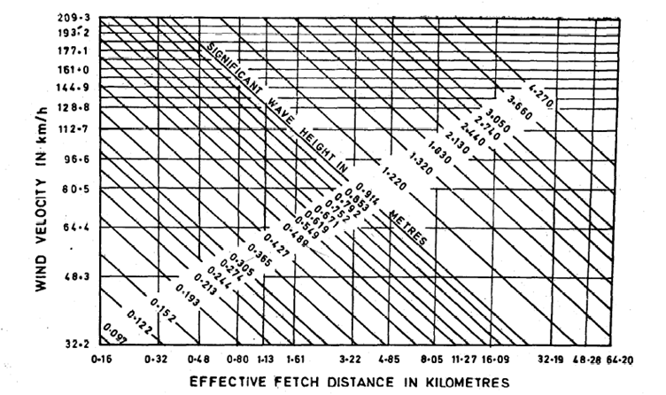
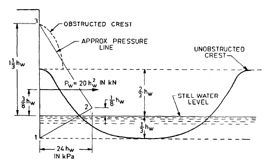
8. WAVE PRESSURE (\(F_8\))
Where, \(h_w\)=height of wave and can be found by following chart
Maximum unit pressure occurs at \(0.125h_w\) above still water level is given by the equation
Total wave force can be calculated by
The Centre of application is \(0.375h_w\) above the sill water level.
9. THERMAL LOAD (\(F_9\))
COMBINATION OF LOADS
As per IS 6512: 1984, the combination of load shall be carried out as follows.
| Comb. no. | Combination name | Loads combination | |
| A. | Construction condition | C1 | F1+F5 |
| B. | Normal operation condition | C2 | F1+F2+F3+F5+F8 |
| C. | Flood discharge condition | C3 | F1+F2(flood)+F3 (flood) +F5+F8 |
| D. | Combination A+ Earthquake | C4 | C1+F4 |
| E. | Combination B+ Earthquake without ice | C5 | C2+F4 |
| F. | Combination C+ Earthquake with extreme uplift (drains inoperative) | C6 | C3+F4 |
| G. | Combination E+ Earthquake with extreme uplift (drains inoperative) | C7 | C5+F4 |